Enhanced Plant Design for Aggregate Processing
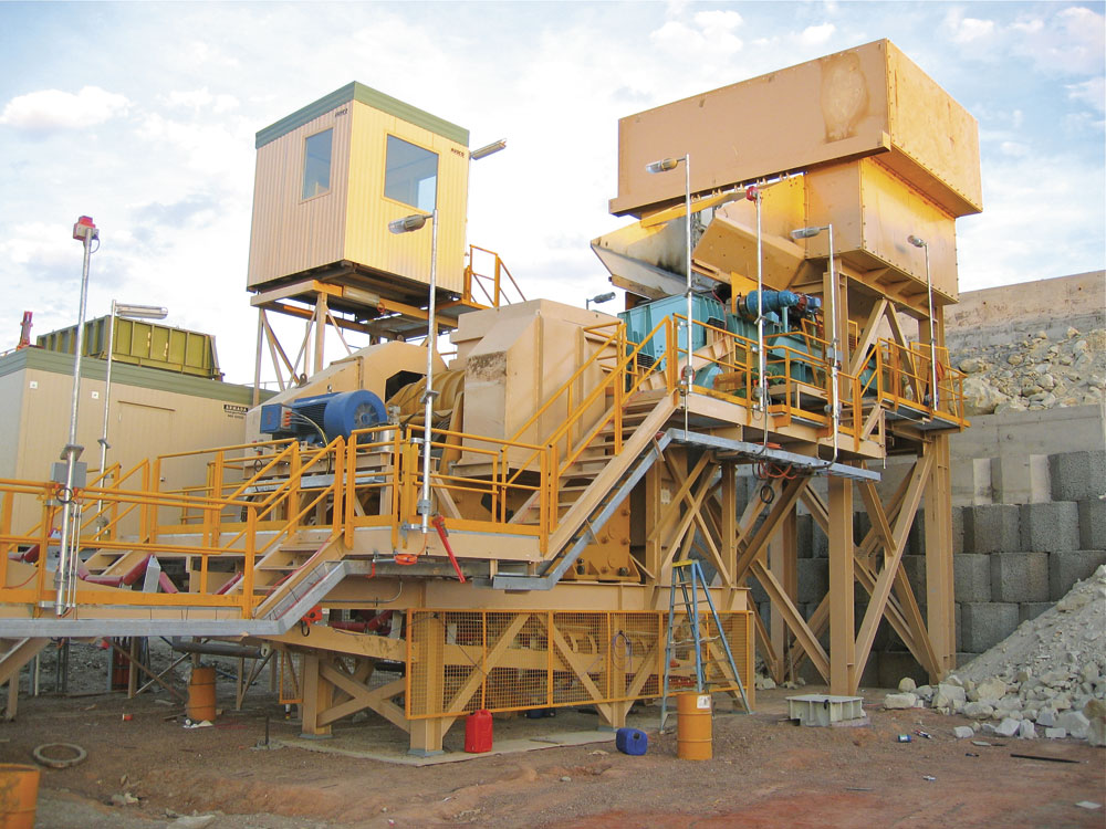
Plant design, refurbishment or extension is dependent on the intended purposes and outcomes of the plant. Steve Mellor explains why enhanced plant design can, in the long term, be critical to the productivity and functionality of a quarry operation
The intention of this article is to provide an overview of matters to be considered when designing a crushing and screening plant, starting with a blank sheet – when planning a plant upgrade or extension, pre-existing factors may overrule the ability to incorporate some or all of these considerations. It is not intended to recommend specific types or brands of machines for the production process, which is a far wider issue, but to concentrate on what aspects should be taken into account in order to design out potential problems and high-maintenance areas, and design in a long service life with maximum plant availability.
For the purpose of this article, the plant under consideration is of a fixed or skid-mounted type, rather than mobile equipment, hence a degree of permanence at the worksite is assumed. Mobile equipment has different needs and conditions to address, many of them different to a static installation.
Before any design work is undertaken, there has to be a clear set of parameters to define the purpose of the plant and what the intended results are to be. The information required would generally be provided from a market survey that would establish the required capacity (with some element of surplus to allow for a growth in the market), product requirements (to be realistically appraised against potential revenue and marketability) defined as sizes of products and levels of quality, and ancillary processes such as washing or de-dusting. There should also be some well-defined data on the physical and chemical characteristics of the proposed in-feed material, essential for specifying the optimum equipment, and consideration of the budget available. Account must also be taken of any environmental or other legal issues that may need to be addressed, as well as implications in terms of cost and time.
Armed with such data, it is then feasible to proceed with the process of flow concept design, and the following are general points to be borne in mind for building an effective crushing and screening plant.
Evaluation and calculation
The intention is to evaluate the content of the plant from in-feed to the plant through the various process stages.
Material is fed into the plant primary section via a primary dump hopper and, while this is a passive component within any plant, its design and sizing are important because:
- it should have sufficient capacity to take the charge from at least two loads and provide sufficient storage for continuous operations
- for any degree of abrasion, with potential for large lump size, a rock box is preferable to sloping sides, albeit at higher cost
- replaceable abrasion-resistant liners have to be fitted in high-wear zones
- an over jaw breaker and lifting beam/hoist are desirable for all plants, and essential on large-scale operations (to avoid operators’ fear of blocking the crusher) where larger rocks are likely to be encountered and the need for continuity of operations is more likely
- the use of a chain curtain can hold back any surges (eg using old track treads etc).
The type of feeder has to be considered and, as with all aspects of plant design, there are pros and cons to each type available. The cheapest may not necessarily be the most suitable in the long term.
The choice would normally be between a vibrating grizzly feeder, a reciprocating tray feeder with a separate grizzly screen, and a apron plate feeder with a separate grizzly screen, and would depend upon operating conditions and the nature of the in-feed, in terms of stickiness and clay content.
Whatever type of feeder is employed, it is strongly recommended that there is some form of separation for bypass, using either the grid section of a grizzly feeder or a separate grizzly screen – and that the cut size is set slightly wider than the closed-side setting (CSS) of the primary jaw crusher. The reason is that there is no point in material passing through the jaw at below or at the CSS as it will cause wear with virtually no reduction in size. However, some in-feed just above the jaw setting is useful as it helps fill the voids. The grid bar spacing prior to the primary crusher is, therefore, a very effective way to enhance capacity within a plant, without compromising overall performance in any way.
In addition to the scalping screen, a separate, small, two- or three-deck screen is a very useful inclusion for processing the ‘unders’ from the scalper. Usually featuring a top protection deck, this can be configured to remove unwanted material from the circuit. The incorporation of a flop gate in the discharge chutes is recommended to maximize versatility, as this allows maximum material to be retained in the crushing circuit when the feed is clean, with the ability to screen out material contaminated with soil, clay etc, when necessary, or to produce low-grade roadbase, drainage or gabion material, for example.
Another recommendation is a short and wide heavy-duty ‘sacrificial’ belt under the jaw, designed to absorb the impact from the jaw product and confine heavy wear to a relatively short belt length, also aiding fines and spillage containment.
For a long-term plant, a strong recommendation is to incorporate a surge pile for the primary product – another example of a passive component contributing to plant efficiency and utilization. The use of a primary surge pile can bring numerous benefits to the production process, increasing profitability, product quality and generally making the operation more versatile, for example:
- The primary crushing section is, inevitably, responsible for the greatest variation in output rates, up to 25–30% or more, so isolating it from the subsequent processes allows a consistent and controlled final process.
- Under most operational conditions, it is viable to run the primary at a different (usually higher) rate than the final process, thereby allowing the two sections to operate for different working shifts.
- Having a ‘live’ capacity of, for example, one full shift’s production allows partial plant shutdowns for maintenance or repairs, without necessarily interrupting the overall production levels of the plant.
- Separating the two sections makes sense from an operational perspective, as the primary operator controls up to the stockpile, a function not capable of successful automation to date, while the main process system can be run in fully automatic mode.
- The two sections would have separate electrical motor controller centre (MCC) units, power feeds, transformers, etc, negating the need for large and costly equipment.
- While a surge pile after the secondary crusher, as is sometimes used, does address this issue to an extent, any selector screen or secondary crusher still has to be sized to meet the peak output from the primary crusher – hence, it is oversized for the average output.
In general, the inclusion of an adequately sized surge pile will pay dividends to the overall operation, with the only significant cost being that of using land area. The use of a luffing conveyor or similar to feed the surge pile should be considered in order to prevent segregation, which is more commonplace in coarser materials.
By using a surge pile with a reclaim system, the load out to the final processing stages is achieved using feeders, housed in a recovery tunnel under the pile. This allows a controlled feed to be delivered to the final processing stages and eliminates the need (and cost) of double handling using loaders etc.
The tunnel is normally manufactured from concrete for long-term installations, corrugated circular-section steel for medium-term use, or even scrap containers for short-term use, subject to compliance with safety standards. The cross-section of the tunnel should allow for the recovery conveyor, feeders and access for maintenance (and emergency escape).
Depending on the type of material and capacity needed, the feeders may be belt or pan type – preferably mounted at 90° to the belt to avoid spillage and contact between large lumps on the belt and the underside of the feeders. With large piles, multiple withdrawal points and feeders are employed to maximize the ‘live’ content from the pile.
Weighing the advantages and disadvantages
The inclusion of a selector screen between the primary and secondary crushers depends on the plant requirements and is, as with any option within a crushing plant design, a compromise; a balance of advantage versus disadvantage. In the case of inclusion, the presence of a screen before the secondary and tertiary crushers allows the load to be split between the secondaries and tertiaries crushers, as well as relieving the total amount to be crushed. The potential downside is that there will be a portion of material in the final product that is not fully crushed on all faces, thereby having a negative effect on shape. However, in practical terms, the total amount of final product in the feed from the stockpile would be a small percentage, usually five to 10%, so it is unlikely to have a serious negative effect.
When using a selector screen in such a location, ie with a substantial percentage of very coarse oversize likely to be present, always allow for an extra deck, with the top deck dressed as a protection/relief deck to prevent undue wear to the media on the middle deck and reduce the bed depth, in order to allow effective operation and avoid rapid deterioration of the screen media.
It may also be useful to consider the inclusion of a variable flop gate in the discharge chute to allow extra products, such as a roadbase or rail ballast material, to be blended and produced at the same time as production of the concrete/asphalt aggregates.
The selection of a suitable secondary crusher depends on a variety of issues and the selection process is not part of this article. The choice is normally between a horizontal-shaft impactor (HSI) and a gyratory or cone crusher. In many instances, a similar situation arises in choosing tertiary crushers.
Numerous factors need to be taken into account when considering the screening process, in terms of design and operational parameters, rather than the actual type of screen. Although specific screens will be selected to suit the actual duty, some general comments on screening are appropriate, for example:
- The ratio between aperture sizes should be maintained as low as possible to prevent excessive bed depth, which reduces screen efficiency, and premature wear from oversize on the thinner media below.
- The use of protection decks is recommended, where applicable, to avoid undue damage to screen media from oversize material – from impact damage as well as increasing bed depth.
- The use of relief decks can result in the ability to use a smaller screen area at the cost of an extra screen deck.
- Generally, the use of more than three decks within any screen is to be avoided as efficiency reduces with each successive deck and the bottom deck is often the most critical, requiring as high an efficiency as is feasible. In some instances, thought should be given to incorporating an additional screen into the circuit, rather than looking at multi-deck versions.
- Selection of screen media – wire, rubber, polyurethane, tensioned or modular – is also a critical factor, with advantages and disadvantages for each. This is a complex subject and decisions need to be made on the basis of case-specific studies.
- While not always an option, wet screening allows much higher capacity for any given screen area, a downside being the need for some form of after- treatment of the slurry.
- Adjustable flop gates can greatly enhance plant flexibility at little cost.
- Features such as isolation frames, rubber mounts and encapsulation can help reduce noise and dust.
When choosing the actual screen, most applications will be covered by the common types – horizontal, inclined, a combination of these (either modular or banana type) and probability screens.
The material will need some form of transfer between successive process stages and, in most cases, delivery to stockpiles or storage bins. Gravity may be employed, using chutes in some cases, and there are sometimes instances where bucket elevators or other devices are employed – however, by far the most common solution is the belt conveyor.
Conveyors are often treated as the ‘poor relation’ in the overall plant design but they do play a very important role and the failure of even the smallest conveyor component within a plant can result in a complete system shutdown until repairs are completed. While it is not within the remit for this paper to dwell on specific design features, attention should be given to some critical areas in order to optimize the conveyor system, for example:
- Running conveyors at a reduced belt speed prolongs component life.
- Never skimp on belt width as under-width belts encourage spillage.
- It is a false economy to use low-cost, small-diameter idlers, generally with smaller bearings, as they run faster at a given belt speed and will have a shorter service life.
- Transfer points should be designed to accept feed from the previous belt without affecting tracking, and to avoid impact and abrasion wear.
- There should be adequate support under the belt to avoid damage and prevent spillage, eg impact beds or similar in impact/feed zones and close-spaced idlers throughout.
- Oversize drives and motors should be employed to permit full-load restarts.
- Encapsulation at transfer points prevents excessive dust emissions.
- The use of sacrificial belts under crushers and high-impact load areas is beneficial to operating costs as high wear and tear is restricted to a short belt only. Also; it is advantageous to use generous width on these short belts to minimize chute height, maintain a steep chute angle and reduce spillage potential.
While the various process machinery, such as feeders, screens and crushers, all play a major part in the overall concept of engineering quality, with the purpose of providing product quality and quality of operations, there are other issues which, although not directly contributing to the flow process or material quality, do have a significant impact on the operational efficiency and costs involved in operating the plant. These include:
- Chute angles to be steep to resist material hanging up in them, especially when damp or sticky.
- Chute outlets to be generously sized, taking into account the material size in them, to avoid potential blockages.
- Chute design and transfer points to take account of trajectory and speed of material in flight, to minimize wear caused by impact and abrasion.
- Generous (and safe) personnel access to be provided for monitoring, maintenance and repairs. This can be augmented by CCTV systems to improve visual observation.
- The use of a wide collecting conveyor under the full screen length allows shallow and steep chutes to be used with no potential for blockage and a reduction in potential wear.
Reaping the dividends over the life of the plant
The purpose of this article has been to draw attention to factors that need to be considered, rather than provide details of all parameters of plant design and configuration. When developing a new project, all the above will need to be looked at, as well as the operational equipment being carefully considered for optimum suitability. Furthermore, continuous and transparent dialogue between the supplier and operator will reap huge benefits in terms of a satisfactory outcome.
The use of a 3D program allows close scrutiny of all aspects of design with an ability to carry out comprehensive virtual inspections prior to final signing-off of the design.
While cost and value for money are important issues, it is rarely the case that the cheapest is the most economical option over the operating life of the equipment, nor that the most expensive will be the best. All equipment has to be thoroughly evaluated to establish value for money. Time spent at the initial and conceptual stages of the design and selection process, and experienced assessment of every factor influencing the production process, movement of materials and environmental considerations, will reap huge dividends over the life of the plant, which is rarely short term. Once decisions have been made and equipment sourced, it is usually too late to introduce significant changes, so the early stages are the most critical.
This article first appeared in Quarry, the official journal of the Institute of Quarrying Australia, and is reproduced here by kind permission.


