Wet Frac Sand Processing

First published in the August 2013 issue of Quarry Management
With interest in shale gas extraction gathering pace in the UK, Chris Kelley, general manager - aggregate processing (US) with McLanahan Corp., looks at the wet processes involved in the production of frac sand, which plays a vital role in the ‘fracking’ process
With the recent boom in both oil and natural gas well drilling using hydraulic fracturing or ‘fracking’ techniques, particularly in the US, there has come an increased demand for both natural and man-made proppants, otherwise known as frac sand. The basic function of frac sand is to create and maintain (prop open) passageways needed for the harvesting of either natural gas or crude oil. Three basic types of proppants are used: natural silica sand; resin-coated silica sand; and ceramic beads.
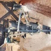
The wet processing of frac sand involves taking natural silica sand proppants from the point of a quarried stockpile of silica sand through to the stockpile that feeds the dryer and final dry sizing process. The basic function of a wet frac sand processing plant is to provide clean sand that is free of clays in the total range of size classifications required by the end user. This size range will vary from one producer to another.
Screening and classification
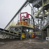
The flow sheet for wet processing typically begins with either a horizontal or inclined primary vibratory screen in either a two- or three-deck design. Horizontal designs are typically used in portable plants or where there are headroom constraints in a stationary plant. Inclined screens utilize gravity while using less horsepower and handling larger tonnages per square foot of screen surface area. The top deck(s) are typically protective deck(s) while the bottom deck provides an 8-mesh separation, depending on the deposit and the end user’s needs. These screens are typically fitted with urethane screen surfaces with slots oriented perpendicular to the flow of materials.
While making the coarse-end separation required, the vibratory screen also provides the introduction point for the addition of water into the process. Water addition begins in the sluicing feedbox and continues with spray bars as the material crosses the screens. The introduction of water in this manner completely hydrates the sand.
In some cases producers will introduce a second screen after the primary screen to provide a finer cut for the coarse-end separation. However, this depends on the nature of the deposit and the ability of a screen to make a separation in the range of 16 mesh, which cannot be made on a primary screen, if required.
Following the coarse-end separation made during screening, the focus switches to making the fine-end separation. After exiting the screening process, hydrated sand in slurry form enters a sump and pump arrangement. The pumps used in this process are typically rubber lined due to the abrasive nature of silica sand.
The sump and pump arrangement typically provides the slurry to a large-diameter hydrocyclone, the primary function of which is to provide feed material to a hydraulic classifier at an ideal density and in a manner that provides even distribution of the slurry into a stilling feed well.
The hydraulic classifier is the key to the wet frac sand process as it provides critical fine separation in preparing the feed for the dry plant. Hydraulic classifiers determine which separation goes into waste and which goes into frac sand. Inefficiencies in the classifier can mistake valuable material for waste, making its recovery impossible. It is important, therefore, to consult with your dry screening supplier to determine equipment requirements for feed size gradations in order to operate at maximum tonnage and efficiency.
The principal of ‘hindered settling’ is core to the operation of the hydraulic classifier when extremely sharp classification is needed to separate granular material by size.
Hydraulic classifiers provide performance comparable to screening at a fraction of the footprint and cost. The separation point can also be easily changed while the equipment is operating by adjusting either the teeter water quantity or the slurry specific gravity set point. The principle of operation is that a column of introduced ‘teeter’ water rising at a certain velocity will carry finer particles of a certain size upwards and over the perimeter weir, while coarser particles of a certain size will sink and exit at the bottom.
There are different styles of hydraulic classifiers available, including flat bottom, cone bottom, cylindrical and square, but the basic operating principle is the same.
Dewatering and attrition
What comes out of the base of the hydraulic classifier is the valuable frac sand part of the deposit. If there are no clays present in the sand the material simply needs to be dewatered and stacked in preparation for the dry plant process. This can be done by using various types of equipment including: horizontal or uphill vibratory dewatering screens; vacuum belts; separators (hydrocyclones) etc.
Dewatering screens have been used for many years and provide a consistently stackable and conveyable material with a moisture content in the range of 10–15%.
Vacuum belts are used in certain facilities because they can provide moisture contents in the range of 4–6% and reduce BTU requirements in the drying process. They are typically utilized where large stockpiles cannot be accommodated due to spatial constraints or where the wet plant discharge goes directly into the dryer via a surge bin.
Dewatering screens are much less expensive and require little, if any, upkeep or operator input, while vacuum belts are expensive and require a consistent bed of solids to operate efficiently (air bypasses if a continuous cake is not present). A simple separator – a hydrocyclone with overflow vacuum control – can be used to dewater the frac sand when there is a great deal of room available at the processing facility and the stockpile can sit for a longer length of time before being fed to the dryer. Moisture levels in the underflow from a separator are higher than dewatering screens, but an extended storage period allows water to drain from the sand.
If there are clays present in the sand it is important that they are liberated and removed, as they can cause turbidity problems which are detrimental to the drillers’ fracking process (clays cut off the passageways for gas and oil). When clays are present in the frac sand product, attrition scrubbers are used directly after the hydraulic classifier. Attrition scrubbers grind the silica particles together in a high-density slurry (65–70% solids) so that the particle-to-particle action liberates the clays clinging to the silica. Generally, a slow-moving, scrubber provides the retention time needed to liberate the clays.
After the clays have been liberated, they must be removed from the frac sand otherwise they can cause serious problems in the dry screening process in terms of both capacity and efficiency. To remove the liberated clays, the sand exits the attrition cells and reports to a sump where water is added to bring the slurry to the ideal density required to feed a separator or hydrocyclone.
The slurry is then pumped to the separator where liberated clays and added water move to and exit from the cyclone overflow, while the frac sand portion moves to and exits from the cyclone underflow. At this point, the frac sand is fed to one of the dewatering options and then reports to a stockpile in preparation for the dry processing plant.
Treatment of non-frac sand material
After stockpiling the frac sand, producers are left with the problem of what to do with the non-frac sand portion of the deposit. In most cases, this is the minus 70-mesh material containing fine sands, silts and clays. Producers need to evaluate the market potential for these materials and determine what size fractions need to be recovered.
They also need to understand their plant’s capabilities regarding settling ponds – eg will they be allowed, what size is available on site, will the settling pond be located on reserves?
Looking at all of these issues will determine what needs to be done with the additional materials from the deposit.
What producers need to understand is that they have the ability to recover and stockpile the plus 140 to 400-mesh portion of the non-frac sand material by means of small-diameter hydrocyclones and linear-motion horizontal or uphill dewatering screens. These systems are available from a number of equipment manufacturers and have been in use in the aggregates industry since the mid-1990s with considerable success. This technology keeps a large portion of material from reporting to settling ponds, which reduces both pond size requirements and the frequency of pond cleaning, and gives producers a marketable additional material.
A large surface area thickener tank can be used to recover the minus 140 to 400-mesh material not recovered by the cyclone and dewatering screen. In the thickener, overflow containing fine solids from small-diameter hydrocyclones is suspended in water and agglomerated into clusters via polymer (anionic) addition, thereby accelerating settling rates. Settled solids are raked to a central bottom-discharge valve for pumping to storage ponds, while reusable process water overflows the tank for immediate reuse in the process plant. Typically, thickeners concentrate the waste water containing suspended solids from 1–2% solids up to 30–40% solids.
The advantages of this process include:
- reduced settling pond size requirements
- reduced energy consumption in pumping of tailings to settling ponds
- immediate reuse of water in process
- allows for use of other technologies to convert these materials to a stackable consistency.
Settling pond elimination
There are various methods which allow for the elimination of settling ponds altogether in frac sand processing plants, including recessed-plate filter presses, belt filter presses, centrifuges etc.
Each of these technologies provides the end-user with a product that is stackable and allows for the complete elimination of settling ponds. It is recommended, however, that producers maintain some ability to store thickener underflow in a surge capacity between the thickener and the equipment mentioned above.
Each of these dewatering technologies provides certain advantages for the producer, who must take into account which solution will work best for their particular application.
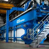
Recessed-plate filter presses are capable of running unattended and allow for the adjustment of moisture content in the filter cake. Moisture content is changed by lengthening or extending the cycle time of the filling process. If the filter cake is to be stored on site and trucks loaded with the material do not need to leave the site, cycle time can be reduced and the cake can contain more moisture, thereby increasing the hourly capacity of the unit. If the filter cake is to be transported off site, it will need to be drier in order to eliminate water dripping from the trucks on to public roads. Another advantage of the recessed-plate filter press is that, unlike belt filter presses and some centrifuges, no further polymer addition is required.
Belt filter presses typically require a fulltime operator to watch over and maintain proper operation. They also require the addition of polymer in order to operate properly and there is very little an operator can do to adjust the moisture content of the discharged cake. These conditions have led to the belt filter press becoming less popular within the industry.
Likewise, centrifuges typically require operators and sometimes require a second addition of polymer in order to operate properly. They offer the ability to adjust moisture content in the cake discharge but moisture levels are typically on par with belt filter presses and higher than those of the recessed-plate filter press. Of additional concern with centrifuges are the tight tolerances and balance requirements in order to maintain proper operation.
Mechanics who work on this type of equipment must be aware of these requirements and the consequences if things go wrong.
- Subscribe to Quarry Management, the monthly journal for the mineral products industry, to read articles before they appear on Agg-Net


