The Right Screen For The Job
A guide to determining the correct screen for the application
Over the years many articles have been written about screen selection and much has been said about the need for better efficiency and bigger throughputs but, unfortunately, a lot of screens fail to live up to the expectations of the operator for various reasons. The following article provides a general guide for use in determining the correct screen for the job.
Screen type
For the purposes of this article an aggregate screen of the kind typically found in a hard rock quarry almost anywhere in the world will be considered, but whatever the application, it is first necessary to determine the type of screen that is required. Contrary to popular belief, there is very little difference, if any, in aggregate products produced by a circular-motion screen compared with a linear-motion screen. Therefore, screen selection at this point comes down to a number of criteria such as personal preference, cost, power consumption, space or planning constraints (installed height etc). Either way, once a decision has been made, the area determination is the same for standard (non-specialist) linear- and circular-motion screens. The transport speed of material on the deck is a function of the screen dynamics; it is possible to have a linear-motion screen transport speed that is greater than that of a circular-motion screen and vise versa.
Quoted feed rates can often be misleading, so if possible it is advisable to visually check for feed stability. Taken to the extreme, if a screen averages 250 tonnes/h but only operates for 15 min in the hour, instantaneous tonnage could be as high as 1,000 tonnes/h. This can happen on batch processes where the average daily plant throughput is considered.
Area requirement
A somewhat contentious issue among screen manufacturers over the years has been the method by which they have sought to determine the screen size for any given duty. Although quite often the methodologies used were similar to each other, most manufacturers made some subtle (and occasionally not so subtle) ‘tweaks’ to the parameters. The end result was numerous screen suppliers all quoting different screen sizes for the same job.
In the US, screen manufacturers were losing face with some very confused customers and hence recognized the need for a common methodology. Following the formation of the Vibrating Screen Manufacturers Association (VSMA), a standardized system of area determination was developed to eliminate such issues. Today, a modified version of this methodology is used; the modifications ostensibly run to using metric instead of empirical units, but the basic principle is the same. However, even this does not guarantee that all suppliers tendering for the same job will quote units that are identical in size, because some manufacturers will still interpret the data differently or may not have the same size standard screens as other suppliers, but they will be a lot closer to each other than in the past.
The screen width can be determined by considering the relationship between the depth of the bed of material and the average particle size or separation size. A good rule of thumb for dry screening is that the depth of bed should be no greater than two-and-a-half to three times the average particle size of material passing over the deck. After determining the overall area requirement, this figure can be divided by the screen width to give the screen length, ie if the area requirement is 9m2 and the width is 1.8m, the screen length will be 5m (9m2 ÷ 1.8m = 5m).
Once the screen size and type have been determined, it is necessary to ascertain the dynamics for efficient screening. Recent studies have shown that selection of the correct stroke, screen speed and inclination will produce the correct particle trajectory, such that a particle resting on a blind area of media will land in an aperture and pass or be rejected. Optimizing this process is the fundamental key to efficient screening. However, while the above premise is fine on a single-separation machine, there will always be compromises on multi-separation screens.
The screen is now optimized from a theoretical perspective, which assumes a number of conditions will be met. For example, it is important to utilize the entire screen surface area, and to do this it is necessary to ensure that the screen is fed full width, ideally via a feedbox or feed tray. Feedboxes are useful in that they not only absorb the impact of the material falling on to the screen, but also start the distribution process, ensuring all available screen surface is utilized. The best method of feeding a screen is with a full-width feeder, belt or chute, so that the material cascades on to the feed tray like a curtain of material. Ideally, material drop heights should be no higher than 300–400mm otherwise damage to the screen and/or screen media may occur.
There should be a minimum of 75mm clearance between static chutework and the screen in the direction of rotation or line of action of the screen, and a minimum of 25mm clearance side to side. A vibrating screen should never be allowed to impact on a static structure while in operation, as serious structural damage to the screens live frame is highly likely. This is why it is important to check for broken springs on a daily basis. A broken spring in one corner will produce a twisting load in the live frame. If this is ignored it can result in cross-member and/or screen sideplate damage.
Wet screening
The addition of water to the screening process can be something of a double-edged sword. While correctly positioned and orientated spray nozzles can vastly improve the passage of material through the screen media, wet screening can have a detrimental effect on the working environment, screen longevity, screen media wear rate and site cleanliness. There have been many rules of thumb applied to the wet screening of aggregate, but ultimately the performance will be determined by the quantity and quality of water available to the screen.
Ideally, between 2.8 and 3.2 gal/min per tonne/h at approximately 2.0 bar is required. Water delivered to the screen through fan-tail nozzles helps wash, turn and ease the passage of material through the media in an efficient manner, reducing the area requirement by a significant amount. However, a damaged or missing nozzle, if it goes unnoticed for any length of time, can result in a hole in the media.
Screen access and egress
Over the years the requirement for screen manufacturers to ensure ease of access to and from within their screens has increased greatly. In the past many manufacturers were keen to supply screens with increasing numbers of decks while minimizing sideplate height, machine weight, installed power and cost. This resulted in machines that were almost impossible to access in order to carry out media changes, let alone conduct preventative maintenance inspections. As a result, screens suffered due to poor maintenance, and aggregate products often went out of specification due to worn panels.
These days things are very different. Today, most screen enquiries tend to stipulate a requirement for ease of access and egress. With the possible exception of plant designers wishing to minimize plant height, this really does benefit all. The screen will benefit from deeper sideplates, providing a stronger more robust live frame, and there will be better accessibility between the decks, aiding media changing and periodic inspections. A number of modular multi-deck screen systems are now available where the upper-deck panels are wider than the lower-deck panels, making it difficult to pass the lower deck but easy to get through the upper media surface to access the space between, while at the same time providing secondary protection (in conjunction with correct harness use) to prevent workers from falling into empty bins.
Screen media
Many types of screen media are available to screen manufacturers and end-users alike, but, without doubt, in the last 20 years the biggest growth area has been in the synthetic media market, with a corresponding decline in the woven-wire market. This is not to say that woven wire is a thing of the past, rather it is more a comment on its popularity compared with two decades ago. The increase in the popularity of synthetics is largely down to their ability to provide a longer service life when directly compared with wire or steel. Modular polyurethane (PU) panels offer a number of advantages, eg a significant reduction in noise nuisance and a reduction in the manual-handling issues surrounding wire or perforated plate.
Many old screens still provide good service and a lot of operators dread the thought of converting their machines to a modular PU system. This is a shame, however, because while woven wire may have a marginally better open area at bigger apertures (eg +20mm), at the smaller end this advantage disappears almost entirely. Experience shows that the loss in performance or throughput is either nil or marginal, and in the case of dynamic membranes actually much better. When this is offset against the vast increase in service life, ease of use and fitting, manual-handling capabilities, and performance and process flexibility, the argument for steel media weakens considerably.
It should be pointed out, however, that some older machines may not be suited to conversion for to a number of reasons, such as poor structural integrity or cross-members being insufficiently strong. If the support frames were to be replaced with heavier items, the additional weight could reduce the machine’s stroke or have a detrimental effect on bearing life, so all these issues need to be investigated before any conversion is considered.
Screen construction and design
There are many methods of screen construction and design. The selection of any particular type of manufacturing method was, and is, largely determined by the manufacturers’ available facilities or a personal preference for a particular manufacturing technique. For some, a fully welded method is preferred, while others stipulate a bolted construction or a combination of several methods.
There are, however, really only two methods of lubrication – either oil or grease. On some machines oil is the only option – generally where there are gears that need splash lubrication – but grease lubrication is often preferred by operators and manufacturers alike.
Screen cross-members come in as many shapes and sizes as there are types of screen, the most popular being circular, square and rectangular hollow sections together with ‘I’ beams and channels. The sectional depth of the screen cross-member needs to be properly calculated to provide sufficient strength to withstand the weight of material on the screen surface plus the media at the operational acceleration. A dewatering screen will carry a lot more weight than a standard sizing screen, so the cross-member depth will need to reflect this. Thermal stress relieving of the support frame is also highly desirable. Some machines use a support frame fabricated as a one-piece assembly while others use individual cross-members. If the design of the screen is of a sufficiently high standard and the unit has been manufactured using quality materials and components, diagonal cross-bracing should not be necessary.
Conclusion
By selecting the right screen for the job in the first place and adhering to as much of the foregoing advice as possible, a screen should meet and even exceed expectations in the areas mentioned above. Optimizing screen performance will save money in the long term. An operator should, therefore, consider spending a little more to ensure that most if not all of the points raised in this article are designed into their next screen.
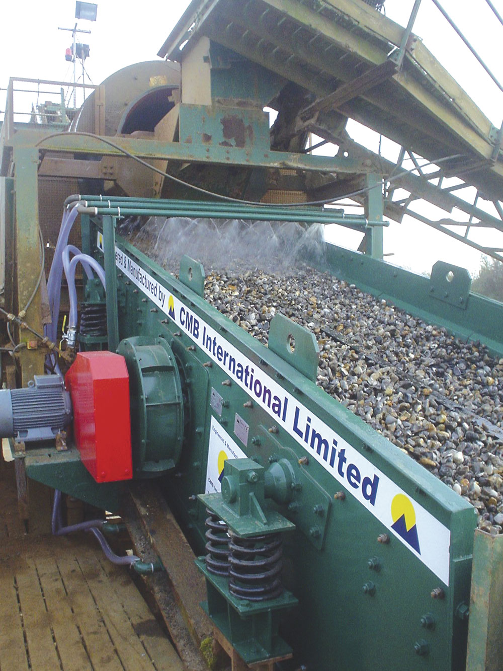
For further information, contact CMB International Ltd on tel: (01530) 563600; fax: (01530) 563900; email: sales@cmb.uk.com; or visit: www.cmbinternational.co.uk