Metering Screw Feeding
Controlling the flow of powders in concrete production
By Dan Liptrott, Rospen Industries
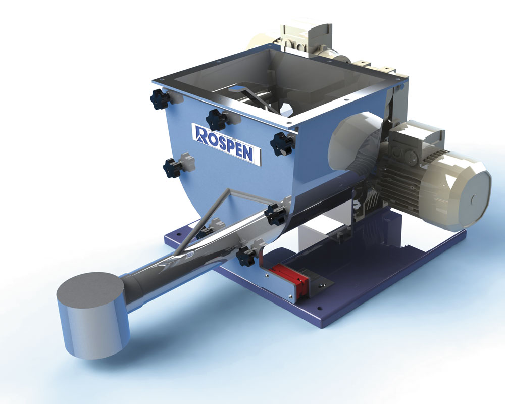
Metering screw feeders are designed to continuously meter all types of materials at constant volumes to very high accuracies. The basic feeder consists of a specially designed, tapered product-conditioning chamber within which is a slowly turning agitator. This article examines the process of controlling the flow of powders into a process at a prescribed rate, such as in concrete production.
Whatever means are employed to actually control the powder, certain basic fundamentals need to be assessed and understood before a solution can be arrived at. First, the terminology used to describe aspects of the equipment is reasonably universal and can be summarized as follows:
Diameter of screw: The nominal outside diameter of the screw (not the diameter of the tube in which it runs).
Pitch of screw: The dimension from one leading face to the next leading face of the screw.
Box loading: The level of material in the tube, usually quoted as a fraction when referring to the screw pitch, ie 1/2, 1/3 etc, and as a percentage when referring to the material loading within the screw tube/casing, ie 50%, 30% etc.
Volumetric feeding: A feeder that meters powder at a specified speed, strictly based on a screw of a known diameter and pitch. Any variation in the powder’s bulk density will cause a direct effect on the feed rate.
Gravimetric or loss-in-weight: A feeder usually identical in design to a volumetric feeder but mounted to a weigh platform to measure the weight lost from the feeder over intervals of time. The main benefit is that any changes in bulk density are detected and allow the screw speed to be varied to maintain the set rate.
PRINCIPLES OF METERING SCREW FEEDING
These can be summarized as follows:
Proper filling of the screw
Otherwise known as entrainment. Correct discharge from the hopper above the screw is essential to ensure starvation does not occur.
Each powder has an ideal speed range through which it will not adversely react to the process of changing direction and filling the pitches of the screw.
Usually, this is determined by trials with the conclusion being that higher speeds will cause more problems, to the extent that some capacities will tail off and not produce straight-line graphs, or accuracy will suffer due to bad entrainment.
Rospen feeders have a particular characteristic in that they are usually linear, so that any increases in screw speed are generally followed by corresponding identical increases in output.
Material flow from the hopper is assisted by two four-blade or spiral agitators which run intermittently or continuously, together with vibrator motors for extreme cases.
For more difficult materials, the standard tapered hopper shape is replaced with vertical hopper sides to ensure consistent flow to the screw.
For larger hoppers (eg more than 150 litres and up to 0.5m3), the use of a vibrating discharge cone together with air evassers arranged asymmetrically about the hopper’s sides, to promote an unstable material bridge in the hopper, should be considered.
In the case of assisted flow, either by the above method or the vibrating-cone bin activators fitted to larger hoppers, care should be taken not to miss-match the output from the discharger and the screw by too big a factor. Compaction between the two can result, causing material which cannot escape to compact and fill the feeder, with the result that the screw bores or tunnels a hole without conveying smoothly.
Alternatively, the problem can be scaled down by batching from large hoppers or silos into the feeder hopper using high- and low-level probes to control the refills from the hopper/silo.
Screw geometry and metering zone
Once the screw size and pitch have been decided, it is important to realize that, to be effective, the pitch of the screw selected must enter the metering zone, ie the discharge tube, for the first three full pitches of the screw. On extended-length screws, the pitch is opened out to reduce the box loading. This has two effects: first, it reduces the stress on the drive shaft of the screw; and secondly, it reduces the power consumption required to drive it. An added benefit is that it alleviates compression of the powder in the case of a problem material.
Screw design: Feeders are supplied in single- and twin-screw configurations. The majority of applications use a single screw with variations in pitch and diameter to suit the application.
Twin-screw feeders are generally used where extreme flushing of powders can occur or, conversely, with cohesive powders, such as pigments or those with a high resin content, which require a large entrainment area to flow properly.
Solid and wire screws: Solid screws, which take the form of a continuous Archimedean spiral with a shaft running throughout the screw, are used in the vast majority of cases. The only additional features of this type of screw are breaker bars set on to the screw in the trough area to break up any dead zone that may form in the trough.
Occasionally wire screws are used. These take the form of a helix spring manufactured from square-section material. It should be noted that wire screws have minimum surface area which does not support significant build-up of cohesive powders.
These also have a downside, however, in that the structure is weaker than a solid screw and more prone to breakage. A shaft can be placed inside a wire screw to help strengthen it, the wire being supported by small pegs from the shaft.
Extended-length screws: In the event that the standard length of feed tube is insufficient and a further extension is required, the following dimensions provide a general rule for the maximum permitted tube length:
- 25mm diameter – 1,000mm
- 40mm diameter – 1,500mm
- 50mm diameter – 2,500mm
- 75mm and 100mm diameter – 3,500mm
It should be borne in mind, however, these lengths are only a guide and will depend on how ‘difficult’ the product is. It will also be necessary to increase the motor power to provide additional torque.
When considering long screws, attempts should be made to reduce the box loading in the tube by sizing the screw diameter with a reduced pitch at the metering point, ie in the trough. Even a 90% pitch at this point, which will give a 10% reduction in the tube, can have marked advantages on the consumed power.
The use of an oversize tube will also assist with cohesive powders, which, when compacted in the normal screw/tube clearance, cause an extreme increase in the power requirement. The increased clearance allows material to run on material in an uncompacted state.
It should be noted that while solid screws can easily be machined to any diameter, pitch or length from solid bar using a fourth-axis milling machine, wire screws, because of their inherent method of manufacture, cannot be so easily changed.
Consistent bulk density
This is a necessity for volumetric feeding but one which client’s often take for granted, assuming the same chemical from different suppliers will have the same characteristics.
Sizing of continuous loss-in-weight feeder hopper
Take the maximum feed rate in kg/h and divide by the material bulk density in kg/m3. This will give cubic metres per hour throughput. Divide by six (ideally a 10min run in gravimetric mode). Multiply the above by 1.3 to allow for the ullage above the net material level, then select nearest size of standard hopper above this.
Example: Size the hopper for 500kg/h continuous duty with material at 800kg/m3.
500 = 0.625m3/h
800
0.625 = 0.104m3 net refill required every 10min
6
0.104 x 1.3 = 0.135m3
Select 150-litre standard hopper.
Problems and possible solutions
Problem: Feed rate keeps dropping before suddenly increasing back to where it was, usually on a cyclic basis.
Solution: Material is building up within the pitch of a solid screw and reducing the carrying volume. Eventually it reaches a point where it cannot sustain its own weight and breaks away, leaving the pitch clear to fill properly again. Replace with a wire screw to cut down surface area for build up.
Problem: Cohesive/sluggish powders.
Solution: Do not attempt to run at maximum speeds and size the screw and pitch to reflect this. Use either twin screws, a wire design or a combination of both.
Problem: Friable granules.
Solution: Slower speed and increased tube diameter with a wire or solid screw will be acceptable.
Problem: Segregation of mixed powder with widely varying bulk densities.
Solution: Try not to use vibration on the hopper and minimize the agitator effect, if possible, to a two-blade intermittent action.
Problem: Extreme pulsing effect from the tube outlet.
Solution: Usually, this becomes more apparent at reduced screw speeds. Fit a cross-wire sleeve to break up the material’s extruded structure.
Problem: Flushing – usually caused by excessive air entrained within the product by a previous operation.
Solution 1: If sufficient time delay cannot be provided within the feeder hopper to condition the material with vibration, consider the use of a large fabricated rotary vane similar to a rotary valve to replace the agitator in the exact same spot over the screw.
Solution 2: Fit close-tolerance discharge tubes and/or increase the number of pitches of the screw by fitting double start blading or half pitch.
Problem: Cannot gain sufficient height to feed into the client’s process from the infeed position.
Solution: Incline the screw, but be careful, as this is invariably leads to an increase in feed centres so the motor power rating must be increased to compensate. With volumetric feeders, simply provide a frame to support the feeder, but in the case of gravimetric feeding, ensure the feeder is suspended from a horizontal weigh frame to improve the stability and accuracy of weighing.
Loss-in-weight or gravimetric feeding
The first issue to remember is that if a powder cannot be handled with reasonable accuracy volumetrically, adding a weighing system to it will not solve the problem and could make matters worse.
Continuous loss-in-weight: Refill rates are critical and should, ideally, be 10 times the output rate of the feeder. When a feeder is refilled it goes into a volumetric mode on the last known signal when in loss-in-weight. Until the weigh platform senses the high level of material in the hopper it will stay in volumetric mode.
After the refill it will, within three seconds, re-learn the loss-in-weight signal and react accordingly.
Obviously, the smaller the refill rate with the screw still discharging product, the longer the volumetric stage on refill and the benefits of loss-in-weight are reduced.
Any size of feeder up to a 150-litre hopper can be mounted to a weigh platform. Larger hoppers will need to be suspended from a weigh frame to ensure the stability of the system.
As with all weighing systems, the main problems are caused by site vibrations, particularly if they have low-frequency, high-amplitude characteristics, such as those emanating from locally sited ball mills or en-masse vibrating-tray conveyors with heavy reaction bases. The fitting of anti-vibration mounts under the feeder/weigh frame can help to limit the effect.
Particularly large-rate loss-in-weight feeders, where control of 20 tonnes/h of product and a refill rate of 200 tonnes/h is required, may not be possible on many installations. Even direct discharge from a silo may not keep up with this rate.
The alternative is to run a continuous flowmeter device, whether screw or belt, together with a volumetric pre-feeder (usually a screw).
The two are run in closed-loop control to maintain the set rate, with the added advantage that the pre-feeder and hopper arrangement, because it is volumetric, does not require the same high rate of refill as the gravimetric control.
The pre-feeder hopper is fitted with high and low level probes to control refills in the conventional sense.
While this solution is invariably more expensive, due to the number of machines employed, it provides a stable and sure method for large feed rates.
Batching loss-in-weight: This uses the same controller (as above) to measure the loss of material from the feeder, but it is set to switch off when a pre-determined target weight is reached on a fast/trickle speed set-up.
While it is ideal to batch in one operation, if it is not possible to install a large enough hopper, multiple runs can be made to make up the batch, as refill rates in this case are not as critical as they are in the continuous loss-in-weight system, due to the cyclic nature of batching operations.
For further information contact Rospen Industries on tel: (01453) 825212