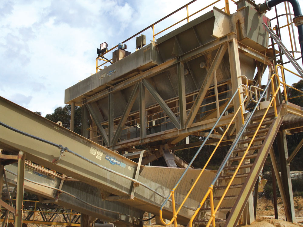
Effective Operation Of Classifying Tanks

Classifying tanks are one of the most efficient methods of washing and classifying sand, but as with all equipment used to process abrasive material, they can become a maintenance nightmare if not operated correctly. Jim Hankins provides some advice on how to make them work more effectively.
Washing sand is actually very simple. Dirty sand and clean water are mixed together, the dirty water is taken away and the end product is a clean sand. To conduct this process efficiently, however, requires experience and knowledge.
Classifying sand is somewhat different, although it can be part of the washing process. Taggart1 describes classifying as ‘an operation in which a mass of grains of mixed sizes and different specific gravities is allowed or caused to settle through a fluid which may be either in motion or substantially at rest’. With sand washing, the particles are essentially of the same or similar specific gravity.
In previous descriptions, the operation of the classifying tank has been said to simulate a river bed. The feed material is introduced horizontally, with the flow of water towards the non-feed end. The water overflows around approximately three quarters of the tank sides, over weirs and is collected for discharge to a pond or subsequent treatment area. Meanwhile, the sand settles throughout the tank, with the largest particles dropping out first, then the medium-sized particles and then the fine-sized particles.
Over the years various illustrations have been used to demonstrate the basic operation of a classifying tank.
A simplified flow diagram of a classifying tank is shown in figure 1.
Controls
Originally, the controls on classifying tanks were all manual, then basic electric and hydraulic devices were introduced. Initial automated controls consisted essentially of proportioning devices. The actual control mechanisms are still basically the same.
Most commonly, classifying tanks have three valves at each station, although four-valve and two-valve tanks have also been produced. With three valves, two products can be ‘controlled’, while a third must exist as a waste or residual product.
Current control and operation of the valves of a classifying tank can be seen in figure 2. A rotating sensing paddle sits above the valve station and when sufficient material settles to stop the paddle’s rotation, a signal is sent to open one of the valves. The controls for this can consist of a PLC, with or without a touch screen for ease of operation, or may include a desktop computer to monitor the opening and closing of the respective valves to maximize yields of the chosen products.
With knowledge of the sieve analysis discharging from each valve station, a recipe or specific gradation can be set up in the operation and re-blending of the valve stations.
Rising-current classifiers
One aspect of control in a classifying tank is the ability to set up a series of rising currents, typically over valve stations 1, 2 and 3. The valve station with a rising current classifier (RCC) is completely enclosed, with an adjustable opening on top. The water introduced in the enclosed area rises through a grate, keeping smaller particles in suspension for longer and cutting out misplaced particles on the coarser valve stations.
Only a brief description of this process is possible in an article such as this. However, the following case study gives some indication of how it may be used.
Case study: Rocla Quarry Products
Rocla Quarry Products have had a McLanahan 10ft x 28ft, eight-station classifying tank for more than 10 years at their Bell Quarry in the Blue Mountains, west of Sydney. They currently use RCCs to maintain a coarse product in the first valve station, while at the same time maintaining the grade on the standard washed sand from the rest of the stations (fig. 3).
The Bell Quarry deposit is a Triassic fluvial sandstone of the Narrabeen Group3. The sandstone is ripped by a dozer and loaded into trucks by an excavator. This material is fed into a trommel equipped with a 6.3mm aperture woven-wire screen. The material that passes through the screen is pumped to the classifying tank.
These two products can be made at the same time, or the normal washed sand can be made on its own. Figure 4 represents Rocla’s washed sand envelope, while figure 5 shows Rocla’s Rel 1 Sand.
Due to time constraints at the time of writing, it was not possible to obtain sufficient data to fully illustrate the above operations. However, data from an alternative site using a nine-station tank is illustrated below.
Figure 6 shows how the particles typically settle in this tank when running without the introduction of RCC water. Interestingly, most curves plotted along these lines (percentage of particle size at each station) approximate to a statistically normal distribution and associated bell curve with each particle size. It should be noted, the 4.75mm material is around 17% at station 1 (16.5% actual), while the 2.36mm material is around 21% (21.4% actual).
Figure 7 shows the same tank running with RCCs in the first three stations. Now the 4.75mm sized material is closer to 30% (28.2% actual) at station 1, and the 2.36mm is similar at 28% (actual).
At Rocla Bell’s operation, as previously mentioned, the RCC in valve station 1 pushes a rising current of water out of the enclosure to keep the smaller-sized particles in suspension and to move them further down the tank. This minimizes misplaced particles in the Rel 1 product. Hence, Rocla are able to make two controlled products through the use of the RCCs in their classifying tank. With minimal 4.75 and 2.36mm sized material in the feed, the RCCs are predominantly increasing the 1.18mm material. In station 1, this increases from approximately 20% without RCC, to around 25% with RCC. Rocla have been making these two products very effectively for several years.
Additional variation in classifying would apply where there is an excess of, for example, the 300 micron and 600 micron sizes. In an eight-station tank, these particles would typically fall around station 5 or station 3 respectively. Hence, the excess could be removed by taking from stations 3 and 5 or any combination of the stations around either of these. Once the amount required to be removed is calculated (most PLC and computer controls will estimate this), the controls then simply need to be set to remove this material.
This article provides a brief introduction to the control of particle distribution and, more importantly, classification in the truest sense while washing sand. The product of classifying tanks, when run correctly, should approximate to 60–65% solids. The underflow, once re-blended, is typically sent to screw washers, as shown in figure 8. More recently, they have been used in applications directly ahead of dewatering screens (fig 9).
As with all equipment used in the processing of abrasive material, if not operated correctly classifying tanks can become a maintenance nightmare. However, when operated and maintained correctly, they are one of the most efficient methods of washing and classifying sand. Classifying tanks do have their limitations, typically water, which is related to the amount of silt in the feed, and sharp separations cannot be achieved. They are, however, able to accommodate large variations in feed material and maintain consistent products with minimal adjustment.
References
- TAGGART, A.F.: Handbook of mineral dressing, John Wiley & Sons, 1945, 1953.
- McLanahan Corp. illustration.
- NSW Department of Mines, 1966.
Acknowledgement
The author, Jim Hankins, managing director of Rivergum Industries, distributors of McLanahan sand and aggregate washing machinery in Australia, would like to acknowledge Rocla Quarry Products for their assistance in preparing this article, in particular the input of John Gardiner and Shane Burton. This article first appeared in Quarry magazine, the official journal of the Institute of Quarrying Australia.


