Feeder Design And Selection
With reference to a recent quarry project, Bob Hill of Skako explains how meeting exact plant requirements requires careful design and selection of feeder options
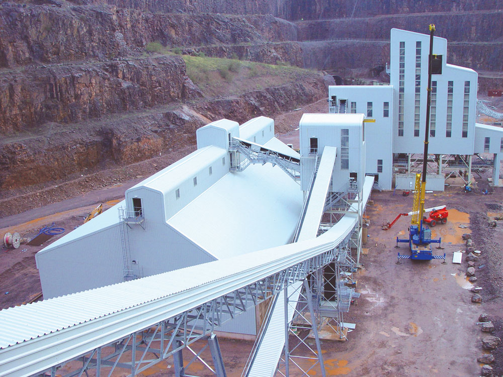
In a recent review of CEMEX’s Taff’s Well project, near Cardiff, in South Wales, reference was made to the use of Skako Comessa vibratory tray feeders. During this project, Skako Comessa liaised in depth with main contractors Whitwick Engineering (Coalville) Ltd to ensure the optimum design for each of the eight vibratory feeder positions.
Many of the new plant’s features bear close resemblance or are even identical in application to another recent CEMEX project at Halkyn, in North Wales, which incorporated 12 Skako vibratory feeders. This project was carried out by the same main contractor and it was on the Halkyn plant that the Taff’s Well feeder design options were proven.
Of the 20 feeders supplied for both projects, 19 were of Skako’s fully modular design, whereby the tray section is fully assembled into a modular unit incorporating an integral flanged hopper bottom section with skirt plates, a manually adjusted bed-depth regulation gate and spring suspension assembly. There were, however, several differing drive types, special design features and both open and totally enclosed dust-proof designs to suit specific locations and duties. A number of these design features are highlighted in greater detail below.
The feeders operating outdoors are fully enclosed and dust-proof. Two identical feeders are located under the primary crushed material surge bin, each discharging into a common central discharge chute positioned over the take-away conveyor (see fig. 1). Each feeder can discharge up to 625 tonnes/h of –350mm primary crusher run material. In order to accommodate the large feed size, while being totally enclosed, the feeder trough has a greater depth than usual and is of heavy-duty design.
Each feeder is driven by twin unbalanced motors (suitable for varying loadings on the feeder) with variable feed rate control between approximately 30–100% provided by means of a frequency inverter. The required plant capacity can, therefore, be achieved by either one of the feeders or by both operating at reduced feed rates. Rod gates were also supplied so either feeder can be isolated for maintenance purposes.
The feeders preceding the secondary and tertiary impact crushers have been designed to spread the material evenly over the width of the impact rotor and to fully integrate with the impactor feed chute arrangement. They are also totally enclosed to prevent safety issues.
For the secondary impactor processing –350mm +75mm material, generally at 450 tonnes/h, the feeder unit is of heavy-duty design, measures 1,800mm in width, features specially increased depth and incorporates a customized support frame to withstand the dynamic loads from the surge bin. Although a feeder of these dimensions would normally be used to deliver over 1,000 tonnes/h, when the size is determined by the width of the impact rotor and not the capacity, it allows smaller drive motors to be utilized, thereby keeping the power consumption to a minimum.
The same design criteria also apply to the tertiary impactor processing –75mm material at 250 tonnes/h. The feeder is 1,000mm wide to evenly spread the feed, but whereas this size of feeder would often be used to handle coarser material at up to 500 tonnes/h, this particular unit only requires half this capacity, with a small maximum feed size. As a result, this feeder is of a compact ‘low-height’ design with smaller drive motors and the discharge end is designed to feed directly into the impactor feed chute (see fig. 2). For both impact breaker feeders, the variable feed rate control is between 30–100% via frequency inverters.
Following final screening inside the main screen house, all coarse sizes are handled on vibratory feeders, allowing the product to be recirculated back to the tertiary impactor, blended with other product sizes or diverted to the load-out stations. Inside the building, the feeders located under the storage bins are all of ‘open’ design, thereby reducing costs. Also, the simpler discharge functions mean standard-sized feeders can be utilized. To give total flexibility over the feed rate and accuracy of discharge, electro-magnetically driven feeders are utilized, giving infinitely variable feed rate control between 0–100% via thyristor controllers, with instant on/off control. The 1,000mm wide feeders can handle up to 400 tonnes/h, with the 800mm wide feeders handling up to 250 tonnes/h at infinitely variable feed rates (see fig. 3).
Plant automation was paramount on both the Halkyn and Taff’s Well projects, by means of a central computerized control system. It was necessary to be able to start and stop the feeders automatically, eg from level detectors in the bins, and also to be able to select the required discharge rates from the control room. This presents no problem for the Skako feeders, because the thyristor controllers for the electro-magnetically driven units are supplied as standard, with a relay for external on/off control, and also integral terminals and a selector switch for automatic regulation from an external isolated reference signal. In addition, frequency inverters were selected with the same control facilities for the unbalanced motor driven units.
The above examples give only a brief insight into the selection of the best feeder design to suit specific applications. For further information, contact Skako Comessa Ltd on tel: (01937) 838010; or email: skakocomessa@btconnect.com