From Local to Cloud-based Condition Monitoring

First published in the May 2017 issue of Quarry Management
Condition monitoring no longer needs to be restricted to highly skilled, experienced engineers. With the advent of cloud-based condition-monitoring systems, users can now share data with experts via the cloud, allowing improved fault diagnosis, faster reaction times and reduced machine downtime, says Dr Steve Lacey, technology centre manager at Schaeffler UK.
Rolling bearings are critical components used extensively in many types of rotating plant and equipment. If they fail unexpectedly, this can result in high repair and replacement costs. Condition monitoring (CM) has been used for many years as an integral part of a predictive maintenance (PM) strategy, and measuring vibration is one of the most widely used CM techniques for detecting and diagnosing equipment faults.
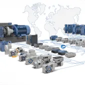
To date, most CM systems have predominantly been used as local systems, collecting vibration data from machines and using analysis algorithms and a rolling bearing database to check for signs of wear, defects or other unusual behaviour. While this works very well for many companies, imagine the added value of being able to share and compare your local machine condition data, via the cloud, with other similar items of equipment across your plant, or better still, with other equipment at multiple plants within your business, wherever they are located in the world. Schaeffler will be offering these cloud-based CM systems from mid-2017.
Furthermore, rather than having to rely on the local knowledge and experience of a skilled maintenance technician, a cloud-based CM system can provide a direct link to a specialist in vibration analysis. These specialists would normally work for a bearing supplier or the supplier of the CM system.
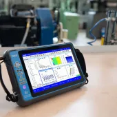
Some CM systems now provide a direct link to the cloud, to which data from CM systems and devices can be transferred. Automated diagnosis signals are processed from the raw data transmitted by the CM system and any other data that is available (eg from the machine’s control system). This means that vibration data is not only processed in the CM system itself – it is also processed in the cloud, which offers greater processing power and more extensive analysis options due to the combination of this data with other machine control data. This increases the reliability of the diagnosis information the customer receives. For highly critical applications, users may also have the option of directly contacting the supplier (via the cloud) of the CM system, who is an expert in vibration diagnosis.
The latest CM systems are quick and easy to install and set up, with the user requiring no specific skills or knowledge of vibration diagnosis. When changes occur in the condition of the equipment, the CM system automatically generates plain text messages on a display, providing the user with clear instructions for action, allowing any corrective maintenance work to be undertaken and any replacement parts to be ordered, if required. These ‘automatic fault assessment’ systems are truly groundbreaking, as they help to minimize the skills, knowledge and experience required of maintenance staff or operators of the equipment.
With ready-to-use, preset measurement configurations, these CM systems can identify the main causes of faults and display them: bearing damage, imbalance, friction/cavitation (for centrifugal pumps) and temperature increases. For general changes in vibration patterns that cannot be clearly attributed to one of the above, the CM system can request, via the cloud, additional analyses from a specialist.
What type of equipment can be monitored?
CM systems can be preconfigured to monitor various types of rotating equipment (typically from 100 rev/min to 15,000 rev/min) that are supported by rolling bearings. These include electric motors, compressors, spindles, cardan shafts, fans/blowers, centrifuges, vibrating screens, fluid pumps, vacuum pumps, gearboxes and geared motors.
Below are examples of some of the more common types of rotating equipment, along with typical monitoring tasks for each, the preferred mounting position for a CM device, and any preconditions for successful monitoring. These are followed by a summary of the benefits for end-customers and OEMs.
Compressors
Typical monitoring tasks: Vibration monitoring of rolling bearings, condition of the gear mesh, screw contacts, drive belt and imbalance.
CM device mounting position: On the compressor housing, radial to the shaft axis. Alternatively, mounted on the motor, radial to the shaft.
Preconditions for successful monitoring: Speed signal is required for variable-speed compressor applications. The ideal machine surface temperature at the mounting position should be below 70°C.
Electric motors
Typical monitoring tasks: Bearing condition, rate of imbalance, electrical condition (phase failure recognition), broken bars in the rotor.
CM device mounting position: On the motor housing, radial to the shaft axis.
Preconditions for successful monitoring: Speed signal is required for variable-speed motor applications. The ideal machine surface temperature at the mounting position should be below 70°C. Should not be installed on the bearing hood (this is a thinner plate with its own vibration). A second CM device may be required for motors above 1MW.
Fluid pumps
Typical monitoring tasks: Bearing condition, imbalance, misalignment, cavitation.
CM device mounting position: On the coupling side of the pump housing, radial to the shaft axis.
Preconditions for successful monitoring: Speed signal is required for variable-speed pump applications. The ideal machine surface temperature at the mounting position should be below 70°C. A load signal may be required for variable media viscosity.
Gearboxes
Typical monitoring tasks: Bearing condition, impact, gear mesh condition.
CM device mounting position: On the gearbox housing, radial to the output shaft axis.
Preconditions for successful monitoring: Speed/load signal is required for variable-speed/load applications. At speeds below 50 rev/min, the monitoring task must be viewed in detail. Depending on the gearbox size and complexity, more than one CM device may be necessary.
Fans and blowers
Typical monitoring tasks: Bearing condition, imbalance, misalignment, as well as acting as a condition guard against severe damage caused by continuous imbalance.
CM device mounting position: On the blower/fan housing, radial to the shaft axis. Plummer block at the fan side.
Preconditions for successful monitoring: Speed signal is required for variable-speed fan/blower applications. A second CM device may be necessary for bearing distances of more than 1.5m.
Benefits for all parties
For the five examples above, there are benefits to be gained for both the end-customer/operator of the rotating equipment and the OEM.
Benefits for end-customers:
- Reduced unplanned shutdowns
- Extended service intervals
- Condition-based cleaning of the surfaces caused by process coatings
- Order OEM service on demand only
- Reduced operational costs by early detection of damage to components, particularly for gearboxes
- Avoidance of hazardous, costly, severe damage, particularly for fans and blowers.
Benefits for OEMs:
- Extended warranty periods
- Identify weak operating areas of a machine (eg resonance)
- New service products (after-sales services) to offer.
- Subscribe to Quarry Management, the monthly journal for the mineral products industry, to read articles before they appear on Agg-Net.com
